Production or working drawings are specialized engineering drawings that provide information required to make the part or assembly of the final design. Working drawings rely on orthographic projection and many other graphical techniques (sectioning, dimensioning, tolerancing, etc.) to communicate design information for production.
Basic Concepts
Engineering drawings are used to
- communicate designs to others (client, colleagues, boss…)
- document design solutions, and
- communicate design production information (to manufacturer).

The documents created in the design stage include
- drawings,
- models (produced with CAD software),
- change orders,
- memos, and
- reports.
For the communication of the final design for production purposes we use the types of drawings which are called working drawings or production drawings.
Working drawings are the complete set of standardized drawings specifying the manufacture and assembly of a product based on its design.
Important
- The complexity of the design determines the number and types of drawings;
- Working drawings may be on more than one sheet and may contain written instructions called specifications;
- Working drawings are the blueprints used for manufacturing products.
Requirements to the set of drawings:
- To completely describe the parts, both visually and dimensionally;
- To show the parts in assembly;
- To identify all the parts;
- To specify standard parts.
Based on the above mentioned criteria, in general, a complete set of working drawings for an assembly includes:
- Detail drawings of each nonstandard part.
- An assembly or subassembly drawing showing all the standard and nonstandard parts in a single drawing.
- A bill of materials (BOM).
- A title block.
Important: Drawings of the standard, off-the-shelf (OTS) components should not be included in the set of the detailed drawings. Exception is when an OTS component is modified (e.g., a standard shaft is cut to the required length). In this case an OTS component turns into custom modified part, and a detailed drawing must be prepared. Such detailed drawing should contain a clear note that this is a standard part (with appropriate notation of the type, catalogue number, etc.), and only parameters/dimensions of modification should be shown.
Thus, the two main types of the drawings in this set are:
- Detailed Drawings
- Assembly Drawings
Structure of the set of working drawings
- High level assembly (assembly of subassemblies, or units, and/or parts);
- Subassembly / subassemblies (Low level assemblies);
- Detailed drawings.
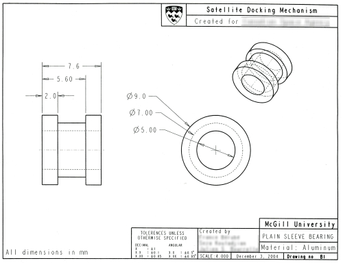
Detailed Drawings
A detailed drawing is a dimensioned, multiview drawing of a single part, describing the part’s shape, size, material, and finish, in sufficient detail for the part to be manufactured based on the drawing alone.
Detail drawings are produced from design sketches or extracted from 3-D computer models.
If the assembly is simple or the parts are small, detail drawings for each part of an assembly can be placed on a single sheet. When more than one detail is placed on a sheet, the spacing between details is carefully planned, including leaving sufficient room for dimensions and notes.
Assembly Drawings
Standard parts (threaded fasteners, bushings, bearings) are not drawn as details because they are normally purchased, not manufactured. However, they are shown in the assembly views.
If you show sectioned assembly, motors do not have to be sectioned.
Bearings should be sectioned when assembly is sectioned.
However, you do not have to draw bearings in full detail: with groove, seals, race, etc. Simplified images are good enough for standard components in assemblies.
An assembly drawing shows how each part of a design is put together. If the assembly depicted is only part of a bigger assembly, it is referred to as a subassembly.
Assembly may consist both of individual original & standard components and of subassemblies of the 1st level.
Subassembly of the 1st level

1st level subassembly may consist of individual original & standard components and of subassemblies of the 2nd level.
Sub-subassembly, or Subassembly of the 2nd level
All assemblies and subassemblies should have their own list of components (parts & units). There can be as many levels of subassemblies as needed for the design. Assemblies and subassemblies can be produced in orthographic technique as well as in axonometric view.
Generally, an assembly drawing consists of:
- All the parts, drawn in their operating position;
- A part list or bill of materials (BOM);
- Leader lines with balloons, assigning each part a detail number, or just with the name of a part, if the assembly is not too big;
- Machining and assembling information and critical dimensions related to these functions.
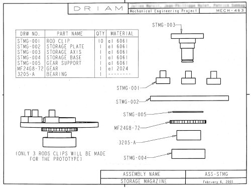
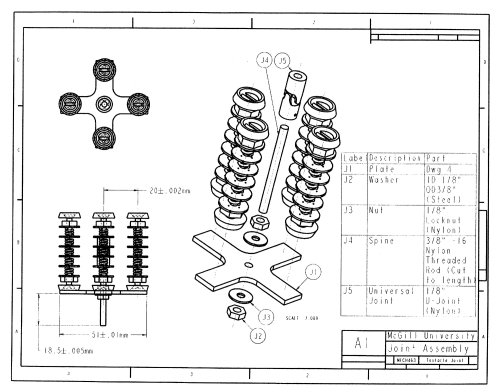
In the figure, the note on the left side view, Only 3 rods clips will be made for the prototype is information of the engineer about the final product.
Assembly drawings are used to both describe how parts are put together and explain the function of the entire unit.
Therefore, in an assembly drawing
- complete shape description is not important;
- the views chosen should describe the relationships of parts; and
- the number of views chosen should be the minimum necessary to describe the assembly (similar to the number of projections needed for a part drawing).
Important:
- Dimensions are not shown on assembly drawings unless necessary to provide overall assembly dimensions, or to assist machining operations necessary for assembly.
- Hidden lines are omitted in assembly drawings, except when needed for assembly or clarity.
Types of Assembly Drawings
There are three basic types of assembly drawings:
- An outline assembly
- A sectioned assembly
- A pictorial assembly
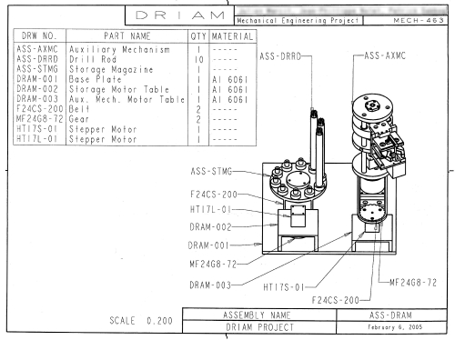
Outline Assembly
An outline assembly gives a general graphic description of the exterior shape, as on this outline assembly drawing of a parallel robot.
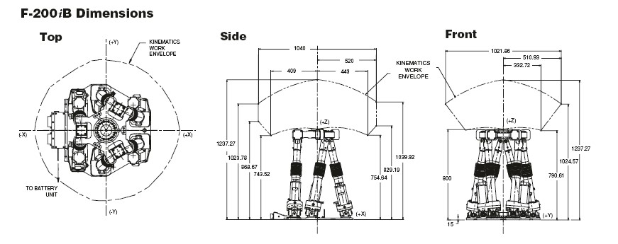
Outline assemblies are used for parts catalogues (general layout of the design) and installation manuals (functionality of the mechanism), or for production when the assembly is simple enough to be visualized without the use of other drawings.
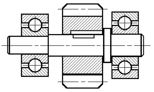
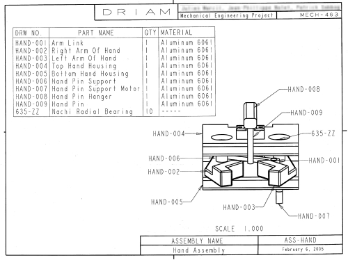
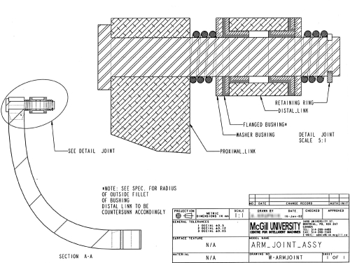
Sectioned assembly
A sectioned assembly gives a general graphic description of the interior shape by passing a cutting plane through all or part of the assembly.
Sectioned assembly drawings are used for manufacturing and assembling complicated devices.
Rules for sectioning assemblies:
- Standard parts, such as fasteners, dowels, pins, and gears, and nonstandard parts, such as shafts, are not sectioned. They are drawn showing all their exterior features. (Ex: fasteners – part N 7, socket head cup screw). Bearings may not be sectioned if the drawing is too crowded.
- Adjacent parts in section are lined at different angles, using the cast iron or other type of symbol.
- Thin parts, such as gaskets, are shown solid black. No sectioning is allowed.
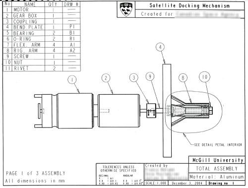
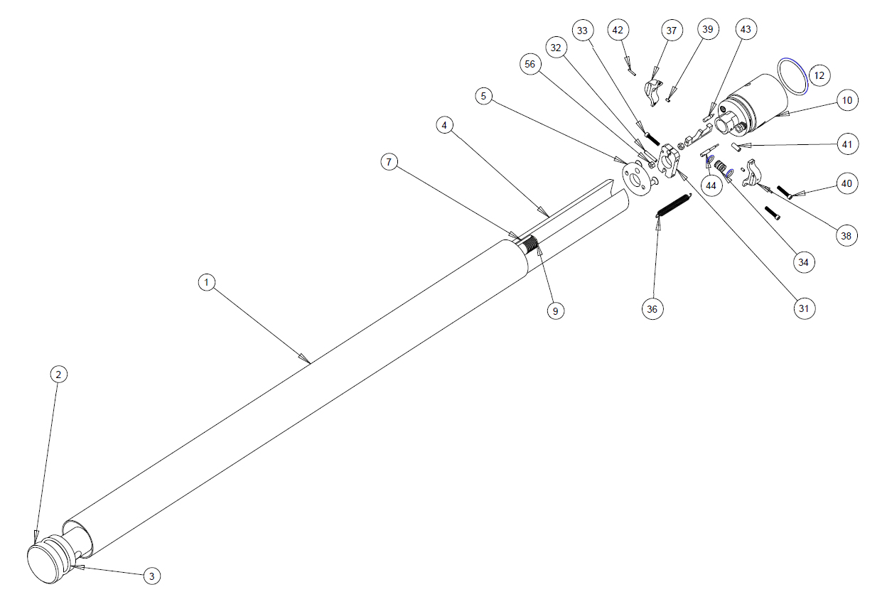
Pictorial assembly
A pictorial assembly gives a general graphic description of each part, and uses center lines to show how the parts are assembled. A pictorial drawing showing the various parts of an assembly, separated but in proper position and alignment for reassembly, is called an exploded view.
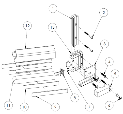
Exploded views are isometric views and are used extensively in service manuals and as an aid in assembling or erecting a machine or structure. Any type of pictorial drawing may be used for this purpose.
Part Numbers and Leader Lines
In all types of assembly drawings every part in the assembly is assigned a part number, which can be a simple number or a string of numbers coded in such a way that a company can keep accurate records of its products. For example, large aircraft have thousands of parts, and considerable documentation is necessary to design, manufacture, assemble, and maintain the aircraft.
Parts are identified in assembly drawings by a leader line with an arrow that points to the part. The other end of the leader has a balloon showing the part number. The names of the parts are given in the list of components.
However, if the assembly is simple, it is possible to use part names with the leaders instead of the balloons with numbers.
Rules of using leader lines:
- Part numbers should be placed outside the general outlines of the parts concerned;
- Each number should be connected to its associated part by a leader line, the termination of which must comply with the standard;
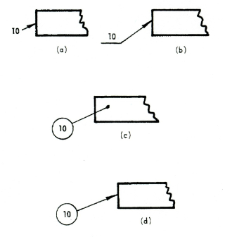
- The leader line may be omitted if the relation between the number and its associated part is evident;
- In the case of encircled numbers, the leader line shall be directed towards the centre of the circle;
- Leader lines should not intersect;
- They should be kept as short as practicable and generally they should be drawn at an angle to the part number;
- For the sake of clarity and legibility of the drawing, part numbers should be arranged preferably in vertical columns and/or horizontal rows;
- Part numbers of related parts (e.g., bolt-nut-washers) may be shown against the same leader line.
A distinct sequence for numbering should be adopted, such as:
- According to the possible order of assembly;
- According to the importance of the component parts (subassemblies, major parts, minor parts, etc.);
- According to any other logical sequence (ex: sequential numbers).
Drawing numbering
Every drawing used in industry is assigned a number. Each company develops its own standard numbering system, based on various criteria such as
- sequential numbers,
- combinations of numbers and letters,
- sheet sizes,
- number of parts in the assembly,
- model numbers,
- function, etc.
Both part numbers and drawing numbers are commonly used to name CAD files and code information for companywide CIM databases.
Bill of Materials
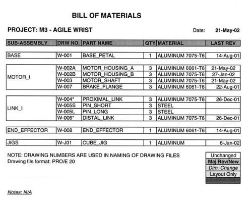
One of the very important concepts of the working drawings is an Item (Part) List, or Bill of materials. A complete set of working drawings must include a detailed parts list or bill of material.
Parts lists or bill of materials (BOM) are complete lists of the items constituting an assembly (or a subassembly) of detailed parts, presented on a technical drawing. Such item lists provide necessary information for the production of the items.
The item list may be included on the drawing itself or be a separate document.
The BOM is divided vertically into columns by means of continuous thick or thin lines to allow the information with regard to the different items to be written in under the following headings (the sequence of these is optional):
- Item – the relevant item reference number as shown on the relevant drawing. Items can be grouped by subassemblies or be placed in a sequential order;
- Name of the part. The “name” column shows the designation of the item. Abbreviations may be used if they do not decrease clarity. If the item describes a standard part (for example, bolt, nut, stud, etc.), its standard designation should be used;
- A detail number for the part in the assembly;
- The part material, for example, cast iron or bronze. This column shows the type and quality of the material to be used. If this is a standard material, its standard designation shall be given, e.g., ASTM A325M;
- The “quantity” – total number of that particular part necessary for one complete assembly;
- The company-assigned part number;
- The drawing number;
- Other information, such as weight, stock size, etc.;
- Information on standard parts, such as threaded fasteners, bearings, motors, includes the part name and size or catalog number;
- The “reference” column with different references – particular specifications, related Standards, etc.
Example of BOM
Title Block
Title blocks are used to record all the important information necessary for the working drawings. The title block is normally located in the lower right corner of the drawing sheet.
Content of the Title Block is described in detail in introduction to Graphics Communication.
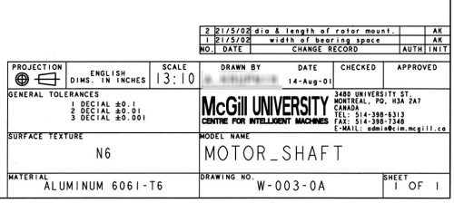
The designations METRIC or SI appear in or near the title block to show that metric dimensions and scale are used on the drawing. Tolerances are specified in a drawing using toleranced dimensions. For those dimensions that are not specifically toleranced, a general tolerance note is used.