Tolerance
Tolerance is the total amount a dimension may vary and is the difference between the upper (maximum) and lower (minimum) limits. Because it is impossible to make everything to an exact size, tolerances are used on production drawings to control the parts.
When do we need tolerances?
In particular, tolerances are assigned to mating parts in an assembly. For example, in case, when the slot in the part must accommodate another part. One of the great advantages of using tolerances is that it allows for interchangeable parts, thus permitting the replacement of individual parts.
Tolerances can be expressed in several ways:
-
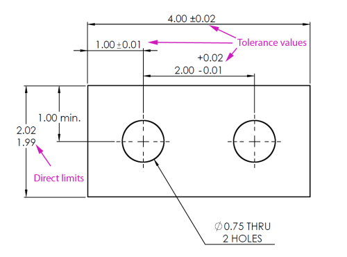
Direct limits, or as tolerance values applied directly to a dimension.
-
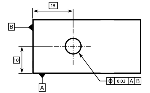
Geometric tolerances, indicated by special symbols related to part surfaces.
-
Notes referring to specific conditions, usually placed next to the corresponding dimensions.
Example: single limit tolerance which limits either the maximum or minimum size of a feature or a space, leaving the other limit of size unspecified.

-
A general tolerance note in the title block.
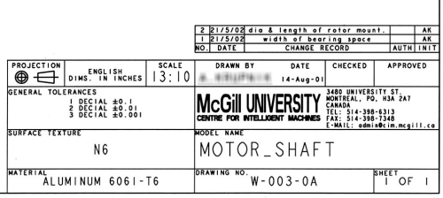
General tolerances are given in a note or as part of the title block.
A general tolerance note:
All decimal dimensions to be held
to ± .002"
This means that a dimension such as .500 would be assigned a tolerance of ± .002, resulting in an upper limit of .502 and a lower limit of .498.
For metric dimensions, the note would be similar:
All metric dimensions to be held
to ± 0.05
This means that a dimension such as 65.00 would be assigned a tolerance of ± 0.05, resulting in an upper limit of 65.05 and a lower limit of 64.95.
If fractional dimensions are used, a general note might be:
All fractional dimensions ± 1/64"
Unless otherwise specified
Angular dimensions can be toleranced through a note such as:
All angular tolerances ± 1 degree
Another general tolerance method would specify the tolerances on dimensions in terms of the number of decimal places found in the dimensions, as follows:
Unless otherwise specified,
Tolerances are as follows:
Decimal inches:
x = ±.200
xx = ±.010
xxx = ± .005
or
Unless otherwise specified,
1 place decimals +/- .1
2 place decimals +/- .03
3 place decimals +/- .008
Millimeters:
x = ± 0.5
x.x = ± 0.3
x.xx = ± 0.1
x.xxx = ± 0.05
In this method, the dimension applied to each feature automatically identifies the required tolerance. Actual tolerances may vary from one company to another, but the ones given here are common tolerances for machined parts.
General tolerances may contain just one set of figures if all dimensions have the same number of decimal places.
If a dimension has a tolerance added directly to it, that tolerance supersedes the general tolerance note. A tolerance added to a dimension always supersedes the standard tolerance, even if the added tolerance is larger than the standard tolerance.
Direct Limits
Tolerances can be applied directly to dimensioned features, using limit dimensioning. This is the ASME preferred method; the maximum and minimum sizes are specified as part of the dimension.

or

Either the upper limit is placed above the lower limit, or when the dimension is written in a single line, the lower limit precedes the upper limit, and they are separated by a dash or by a slash:
3.49 - 3.53 3.49/3.53
Plus and Minus Tolerances
With this approach the basic size is given, followed by a plus/minus sign and the tolerance value.

Diagram: (A) Unilateral tolerances; (B) Bilateral tolerances.
Tolerance can be unilateral or bilateral. A unilateral tolerance varies in only one direction, while a bilateral tolerance varies in both directions from the basic size.
If the variation is equal in both directions, then the variation is preceded by a + symbol. The plus and minus approach can only be used when the two variations are equal.
Important terms
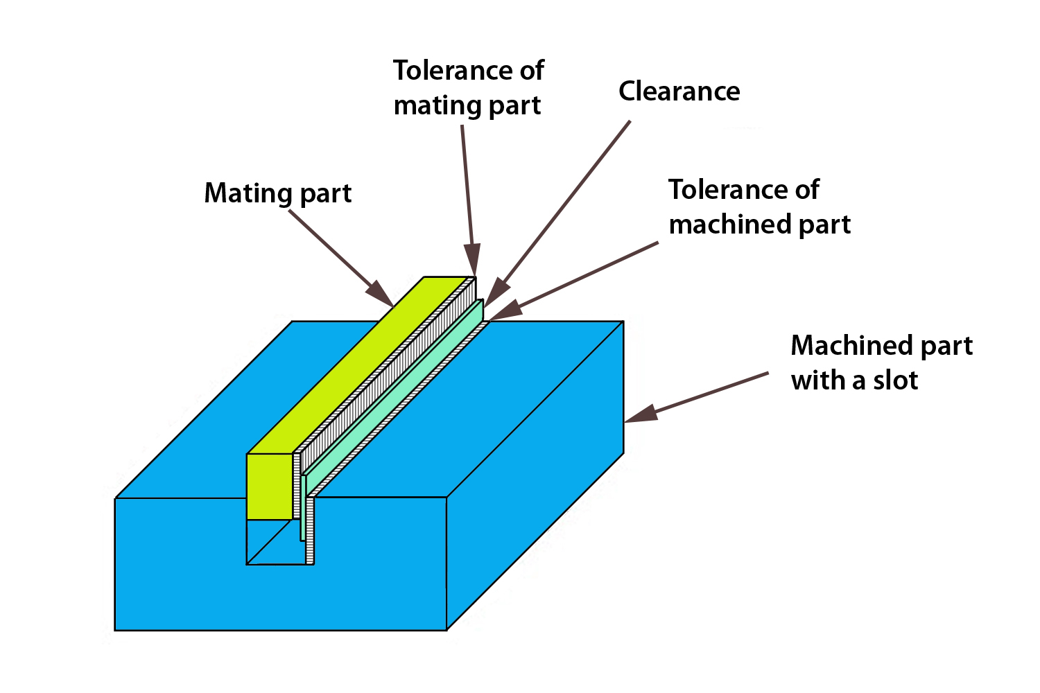
The figure shows a system of two parts – machined part with slot and mating part - that have toleranced dimensions. These two parts are used as an example in ASME/ANSI standard to define important terms.
- Nominal Size – a general size, common fraction.
- Basic size – the theoretical size used as a reference for the application of tolerances. This size is shown o the drawings in a rectangular box.
- Actual size – actual measured size of the finished part after machining.
- Limits of size – the maximum and minimum permissible sizes between which the actual size should lie. The larger value for each part is the upper limit, and the smaller value is the lower limit.
- Allowance is the minimum clearance or maximum interference between parts, or the tightest fit between two mating parts.
Example: The slot and the mating parts have basic dimensions of 0.500 inches. Lower and upper limits of the slot are 0.498 and 0.502 inches, correspondingly; lower and upper limits of the mating parts are 0.495 and 0.497 inches.

In the above figure, the allowance is 0.001, meaning that the tightest fit occurs when the slot is machined to its smallest allowable size of 0.498 and the mating part is machined to its largest allowable size of 0.497. The difference between 0.498 and 0.497, or 0.001, is the allowance.
Tolerance is the total allowable variance in a dimension, i.e., the difference between the upper and lower limits. The tolerance of the slot in the example is 0.004" (0.502 - 0.498 = 0.004) and the tolerance of the mating part is 0.002" (0.497 - 0.495 = 0.002).
Fit types
The degree of tightness between mating parts is called the fit.
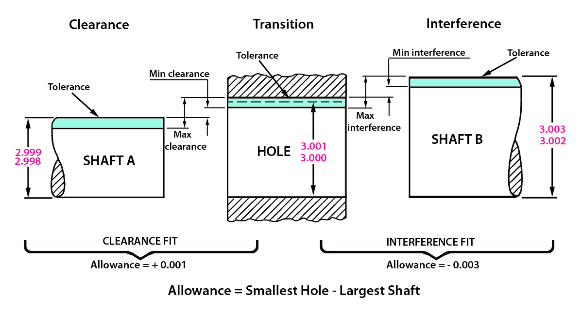
Diagram: Clearance - Transition - Interference; Clearance Fit (Allowance = + 0.001); Interference Fit (Allowance = - 0.003); Allowance = Smallest Hole - Largest Shaft.
Clearance fit
Clearance fit occurs when two toleranced mating parts will always leave a space or clearance when assembled. In figure above, the largest that shaft A can be manufactured is 2.999, and the smallest the hole can be is 3.000. The shaft will always be smaller than the hole, resulting in a minimum clearance of +0.001, also called an allowance. The maximum clearance occurs when the smallest shaft (2.998) is mated with the largest hole (3.001), resulting in a difference of +0.003.
Interference fit
Interference fit occurs when two toleranced mating parts will always interfere when assembled. An interference fit fixes or anchors one part into the other, as though the two parts were one. In the figure, the smallest that shaft B can be manufactured is 3.002, and the largest the hole can be manufactured is 3.001. This means that the shaft will always be larger than the hole, and the minimum interference is -0.001.
The maximum interference would occur when the smallest hole (3.000) is mated with the largest shaft (3.003), resulting in an interference of -0.003.
To assemble the parts under this condition, it would be necessary to stretch the hole or shrink the shaft or to use force to press the shaft into the hole. This kind of fit can be used to fasten two parts together without the use of mechanical fasteners or adhesive.
Transition fit
Transition fit occurs when two toleranced mating parts will sometimes be an interference fit and sometimes be a clearance fit when assembled.
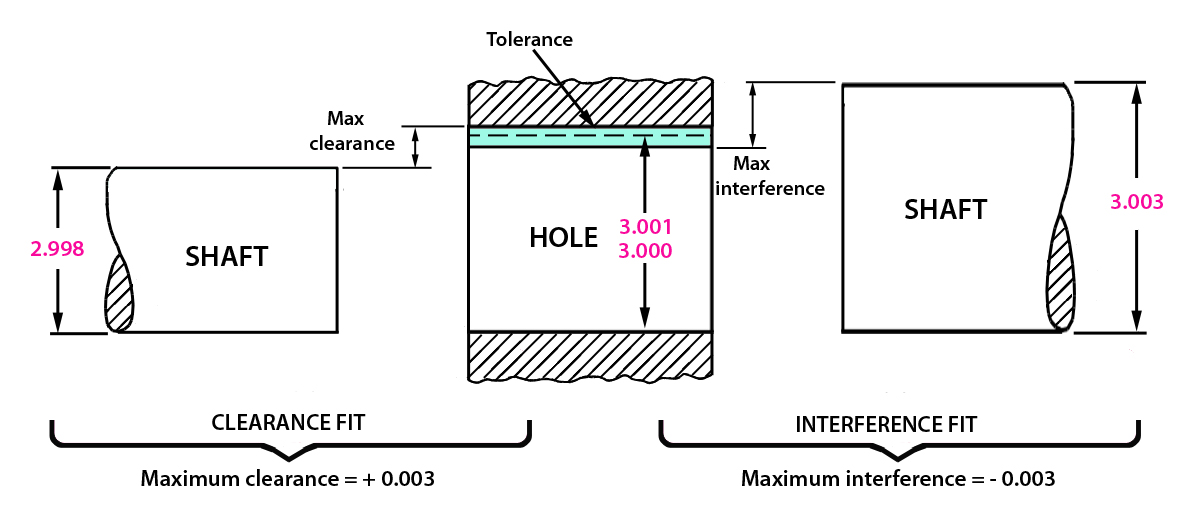
Diagram: Clearance Fit (Maximum clearance = + 0.003); Interference Fit (Maximum interference = - 0.003).
In the figure, the smallest the shaft can be manufactured is 2.998, and the largest the hole can be manufactured is 3.001, resulting in a max clearance of +0.003. The largest the shaft can be manufactured is 3.003, and the smallest the hole can be is 3.000, resulting in a max interference of -0.003.
The loosest fit is the difference between the smallest shaft and the largest hole. The tightest fit is the difference between the largest shaft and the smallest hole.
Fits for holes and shafts

Diagram: Clearance Fit (Loose fit, Free fit, Medium fit, Snug fit); Transition Fit (Wringing fit, Tight fit, Medium force fit); Interference Fit (Heavy force and shrink fit).
The additive rule for tolerances is that tolerances taken in the same direction from one point of reference are additive. The consequence is that tolerances to the same point taken from different directions become additive. This may happen during assembling of two parts, when accumulated tolerances of positions of mating points of both components are also summarized. The effect is called tolerance stack-up.
Metric limits and fits
The standards used for metric measurements are recommended by the International Organization for Standardization (ISO). The terms used in metric tolerancing are:
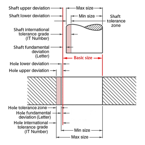
- Basic Size – the exact theoretical size to which limits of deviation are assigned and are the same for both parts.
- Deviation – the difference between the size of the part and the basic size.
- Upper deviation – the difference between the maximum size limit and the basic size.
- Lower deviation is the difference between the minimum limit of size and the basic size.
- Fundamental deviation is the deviation closest to the basic size (for both parts). It is denoted by a letter.
- Tolerance is the difference between the maximum and minimum size limits on a part.
- Tolerance zone represents the tolerance and its position in relation to the basic size.
International tolerance grade (IT)
International tolerance grade (IT) – the classification system – representing groups of tolerances which vary depending upon the basic size but have the same level of accuracy with a given grade. It is denoted by the combinations IT0, IT1, and IT01 to IT16 – altogether 18 IT grades.
Relation of Machining Processes to Tolerance Grades

Practical Usage of IT Tolerance Grades

For example, in the following figure with the notations of hole, shaft and their free running fit, the number 9 is IT grade.

Hole basis is the system of fits where the minimum hole size is the basic size. In the example, the fundamental deviation for a hole basis system is indicated by the uppercase letter “H”.
Shaft basis is the system of fits where the maximum shaft size is the basic size. In the example, the fundamental deviation for a shaft basis system is indicated by the lowercase letter “d”.
Metric Tolerance Symbols
Combining the IT grade number and the tolerance position letter establishes the tolerance symbol, which identifies the actual upper and lower limits of a part.
The tolerance size of the part is defined by the basic size followed by a letter and a number, such as 60H9 or 60d9.
For example the notation of a metric fit would appear as 60H9, where:
60 The basic size of 60 millimeters.
H Fundamental deviation of an internal feature (hole).
9 A free running clearance fit.
Here are the three methods of designating metric tolerances on drawings:

The types of fits with corresponding letter and number symbols, as well as with upper and lower tolerance limits can be taken from the tables available in mechanical engineering handbooks.
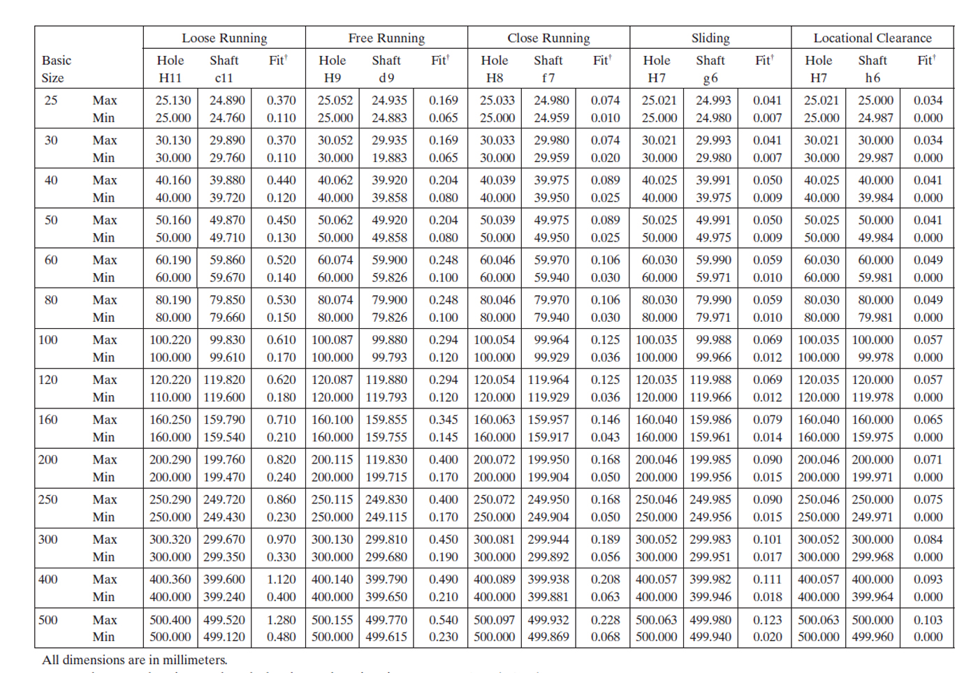
This is a hole basis table. The hole basis system for clearance, interference, and transition fits means that the fundamental deviation of the hole (i.e. difference between the minimum size limit and the basis size) is zero.
The hole based system of fits

If the shaft basis system for clearance, interference, and transition fits is used, that means that the fundamental deviation for shaft is zero.
The metric preferred shaft basis system of fits in this case is:

The description and application of the hole basis system and shaft basis system are given in the following table:

| -- | ISO Symbol | Description | Condition | |
|---|---|---|---|---|
| Fits | Hole Basis | Shaft Basis | Types of fits |
↑ More |
| Transition | H11/c11 | C11/h11 | Loose running fit for wide commercial tolerances or allowances on external members. Free running fit not for use where accuracy is essential, but good for large temperature variations, high running speeds, or heavy journal pressures, Close running fit for running on accurate machines and for accurate location at moderate speeds and journal pressures. Sliding fit not intended to run freely, but to move and turn freely and locate accurately. |
|
| H9/d9 | D9/h9 | |||
| H8/f7 | F8/h7 | |||
| H7/g6 | G7/h6 | |||
| Clearance | H7/h6 | H7/h6 | Locational clearance fit provides snug fit for locating stationary parts; but can be freely assembled and disassembled. Locational transition fit for accurate location, a comprise between clearance and interference. Locational interference fit for more accurate location where greater interference is permissible. |
|
| H7/k6 | K7/h6 | |||
| H7/n6 | N7/h6 | |||
| Interference | H7/p61 | P7/h6 | Locational interference fit for parts requiring rigidity and alignment with prime accuracy of location but without special bore pressure requirements. Medium drive fit for ordinary steel parts or shrink fits on light sections, the highest fit usable with cast iron. Force fit suitable for parts which can be highly stressed or for shrink fits where the heavy pressing forces required are impractical. |
|
| H7/s6 | S7/h6 | |||
| H7/u6 | U7/h6 |
↓ More Interference |
||
1 Transition fit for basic sizes in range from 0 through 3 mm.
Fitting bearings (Example)
Most commercial bearings are produced to metric dimensions → the fits are specified according to the tolerance system of the ISO.
Recommended tolerance grades for the bearing seats on shafts and housing bore fits with the outer race (for bearings carrying moderate to heavy loads):
| Bearing Bore Diameter | Range Tolerance Grade |
|---|---|
| 10-18 mm | j5 |
| 20-100 mm | k5 |
| 105-140 mm | m5 |
| 150-200 mm | m6 |
| Housing bore (any) | H8 |
The bearing bore and bearing outer diameter are those expected from the bearing manufacturer.
You must control the shaft diameter and the housing bore to the specified minimum and maximum dimensions.
- The Bearing Bore / Shaft fit is mainly a transition fit for accurate location (compromise between clearance and interference, or more interference) – j, k, m.
- The Housing / External Race fit is a clearance fit (close running fit for accurate location at moderate speeds and moderate load) – H.
How can bearings be fixed/located on the shaft or in the hole?
The simplest way is press fitting.
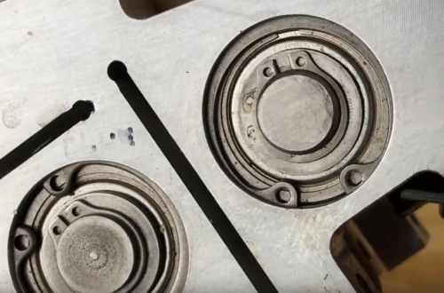
Instead of press fitting (especially in case of a running fit) you may and sometimes should use means of axial location: retaining rings, collars, shoulders, spacers or locknuts.
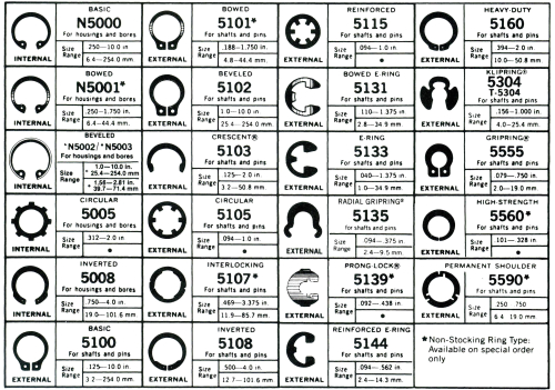
Retaining rings – placed on a shaft, in grooves in the shaft, or in a housing to prevent the axial movement of a machine element.
Types of retaining rings
Shoulder – a vertical surface produced when a diameter change occurs on a shaft.

Spacer – a ring slid over the shaft against the machine element that is to be located, i.e. it is positioned between two elements and thus controls only the relative position between them.
Locknut – can be used when an element is located at the end of the shaft. Needs the thread on the shaft and a locking device.
Lockwasher can be added to fix the locknut.
Collar – a ring similar to a spacer slid over the shaft, but positioned adjacent to a machine element for the purpose of axial location. It is held in position, typically, by set screws, and axial location can be set virtually anywhere along the shaft.
Adapter Sleeve – similar to collar, but with tapered outer surface and a slit, and is placed between the bearing and the shaft. Locknuts are used to clamp the sleeve.

English unit fits
Similar to the metric system, a special group of English unit tolerance relationships, called preferred precision fits, have been developed. ANSI Standard B4.1 specifies a series of standard fits between cylindrical parts, based on the basic hole system.
The different fit classes are as follows:
- Running and sliding fit (RC) – the loosest of the fit classes, when a shaft must move freely inside a bearing or hole, and the positioning of the shaft is not critical.
- Clearance location fit (LC) – tighter than the RC class fits, but the shaft and hole may be the same size, which is called a line-to-line fit. Shaft is located more accurately, but it may still be loose.
- Transition location fits (LT) – a transition between LC an LN fits.
- Interference location fits (LN) – here the shaft can be line to line with the hole, but it is almost always larger than the hole. Is used where a part must be positively located relative to another part.
- Force and shrink fit (FN) – pure interference fit, where the shaft is always considered larger than the hole. Is used to transmit torque; to secure a bearing or pulley to a shaft, even if there is a twisting force; or to anchor parts that may slide along a shaft.
Also, like the metric system, there are basic hole and basic shaft systems for applying English unit tolerances to parts. It depends on whether the basic size refers to the size of the largest shaft or the smallest hole.