Threaded fasteners
Fastening is a method of connecting or joining two or more parts together, using processes or devices.
- Processes: welding, gluing, soldering;
- Devices: bolts, screws, anchors, etc.
One of the most common methods used for fastening is mechanical fastening, a process that uses manufactured devices such as screws, pins, or rivets to hold parts of an assembly together. A threaded fastener is a mechanical fastener used to join two or more parts.
Thread specifications: English system
To specify a thread using the English system, you must provide a minimum of five pieces of information:
- Thread form
- Thread series
- Major diameter
- Class of fit
- Threads per inch
Thread form is the shape or profile of a screw thread. Many types of thread forms have been developed.
- The sharp-V thread was originally developed by William Sellers (September 19, 1824 – January 24, 1905), a mechanical engineer, manufacturer, businessman, and inventor who filed more than 90 patents.
- The American National thread replaced the sharp-V thread and is stronger than the sharp-V thread.
- The Unified thread is the current standard used in the United States, Canada, and England.
- A variation on the Unified thread is the Unified National Round thread, abbreviated UNR.
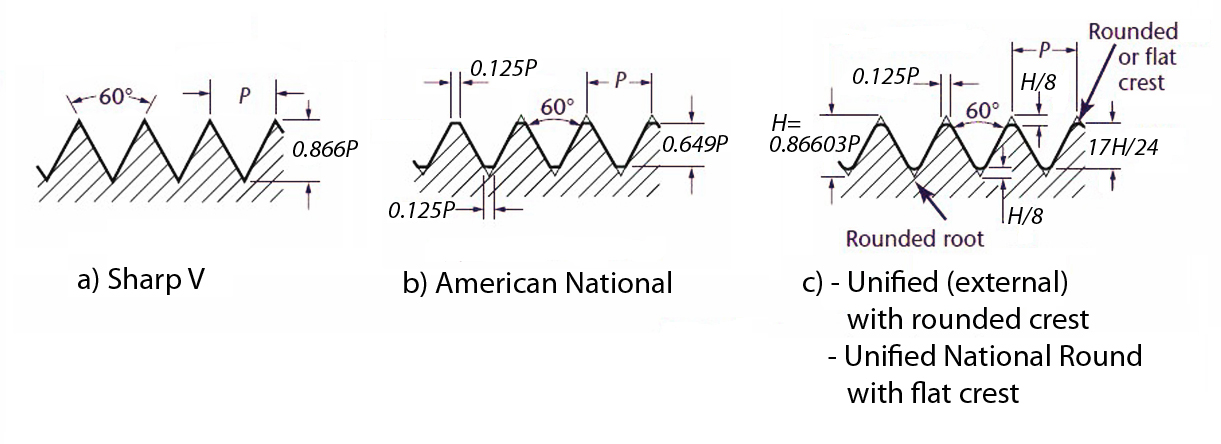
Diagram: (A) Sharp V; (B) American National; (C) Unified (external) with rounded crest and Unified National Round with flat crest.
- The metric thread is the international standard thread, similar in shape to the American National thread.
- The square, Acme, and buttress threads are used to transmit power in gearing and other types of machines.
- The knuckle thread is usually rolled from sheet metal or cast, and it is used for lightbulb bases, bottle caps, and glass jars.

Diagram: (D) Metric; (E) Square; (F) Whitworth standard; (G) Acme; (H) Knuckle; (I) Buttress.
The thread series refers to the standard number of threads per inch, and there are four classes: coarse (C), fine (F), extra fine (EF), and constant pitch. When used with the Unified thread, they are abbreviated UNC, UNF, and UNEF. The constant pitch series is specified by writing the number before the form designation (4, 6, 8, 12, 16, 20, 28, 32).
- Coarse series fasteners are used for quick assembly or disassembly of cast iron, soft metals, and plastic, and are designated NC or UNC.
- Fine series fasteners are used when a great deal of force is necessary for assembly, and are designated NF or UNF. These fasteners are used extensively in the aerospace and automotive industries.
- Extra fine series fasteners are used when the length of engagement is short and the application calls for high degrees of stress.
- Constant pitch series threads are for special purposes, such as large-diameter or high-pressure environments. It is used when the Coarse, Fine, Extra-Fine Series do not meet the design requirements, and within these series, preference should be given to the 8, 12, and 16 thread series.
There are three classes of fit established by ANSI for general use.
- Class 1 - a loose fit where quick assembly is required and looseness or play between parts is acceptable.
- Class 2 - a high-quality, general purpose, commercial class of fit for bolts, nuts, and screws widely used in mass production.
- Class 3 - a very high-quality threaded fastener with a close fit, used for precision tools and for high stress and vibration applications.
Threads are only symbolically represented on drawings; therefore, thread notes are needed to provide the required information. A thread note must be included on all threaded parts, with a leader line to the external thread or to an internal thread in the circular view.

External thread notes are given in the longtitudinal view. Internal thread notes are given on the end view, with a pointer to the solid circle.
A thread note should contain the following information:
- Major diameter in fraction or three place decimal form.
- Number of threads per inch, followed by a space.
- Thread form designation.
- Thread series designation.
- Thread class designation (1,2, or 3).
- Internal or external symbol (A is for external threads, B is for internal threads), followed by a space.
- Qualifying information, such as:
- LH for left hand threads. If the thread is right-hand, RH is omitted.
- DOUBLE or TRIPLE for multiple threads.
- Thread length.
- Material.
Thread specifications: Metric system
Metric thread specifications are based on ISO recommendations and are similar to the Unified standard. The basic designation for a metric thread are:
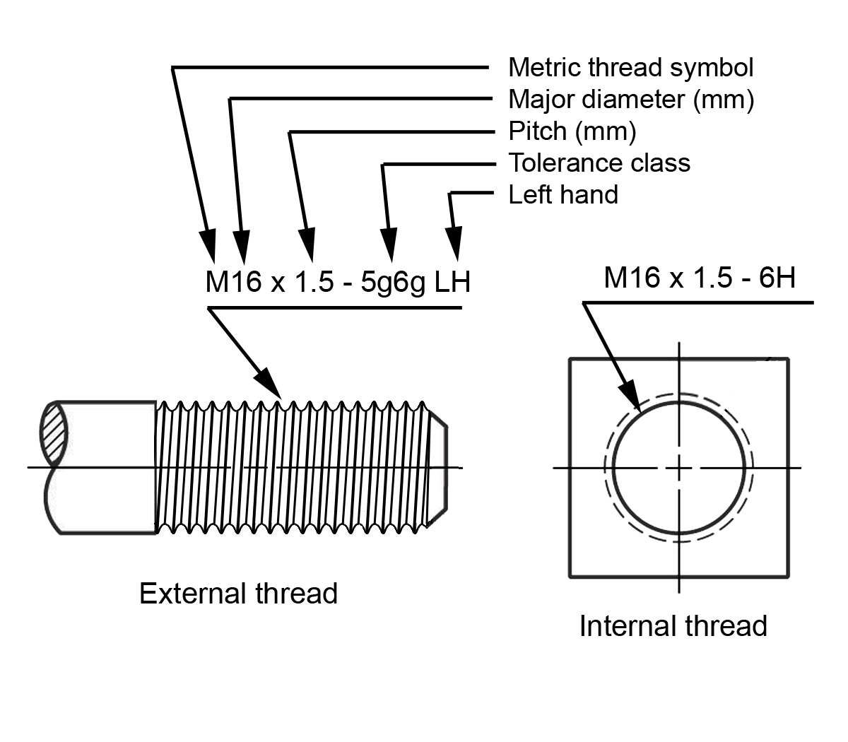
Here, the note specifies that the thread is metric (M), the diameter of the thread is 16 millimeters, followed by the multiplication sign ‘x’, and the pitch is 1.5 millimeters.
Generally, a complete metric thread note should contain the following information:
- Thread form symbol. The letter M is used to designate the metric profile. The J profile class is a modified M profile.
- Nominal size (basic major diameter) in millimeters, followed by an ‘x’.
- Pitch in millimeters, followed by a dash. The pitch can be eliminated for coarse threads, but it is preferred in the American use of the standards.
- General purpose tolerance. The tolerance class designation includes:
- Pitch diameter tolerance: grade, position
- Minor diameter tolerance: grade, position.
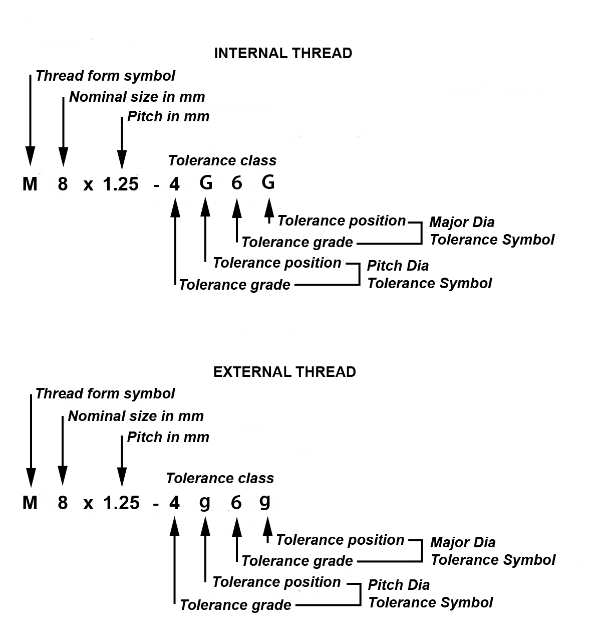
Diagram: Internal thread; External thread.
For external threads tolerance lowercase letters are used, for internal threads – uppercase letters.
Screw thread representation
Two types of conventions are in general use for screw thread representation, conventional and alternative (pictorial) representation.
Conventional Representation should be used whenever it communicates the required information without confusion, as it requires the least amount of drafting effort.
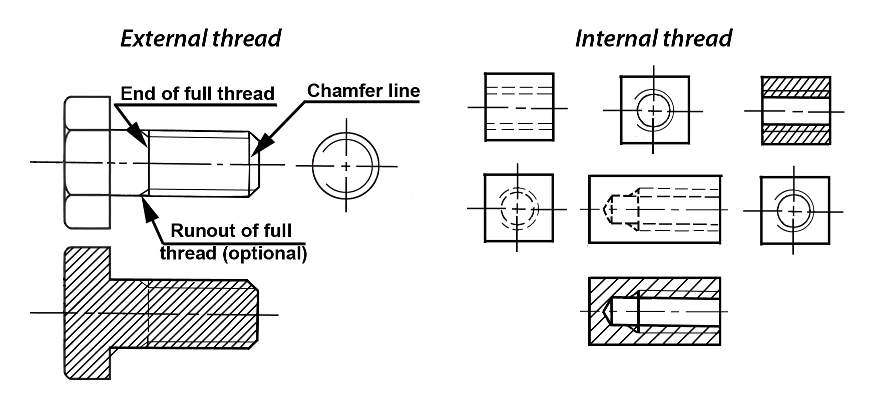
Diagram: Internal thread; External thread.
This method is independent of the type of screw thread. The type of screw thread and its dimensions have to be indicated.
The alternative representation requires more drafting time but is sometimes necessary to avoid confusion with other parallel lines, or to more clearly portray particular aspects of the thread. This is a close approximation to the actual appearance of the screw thread:
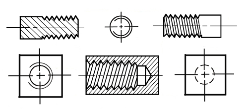
It is simplified, so that crest and roots for full threads are shown sharp, with single straight lines instead of the double curved lines that would be required for the flat crests and roots.
Alternative representation should be used only for enlarged detail and other special applications.
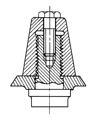
Threaded assemblies
For general use, the conventional representation for assemblies of threaded parts is recommended.
In sectional views, the externally threaded part is always shown covering the internally threaded part (bolt thread is shown, hole thread is not shown).

Both methods can be used simultaneously on the same drawing.
Rolled threads
External threads may be cut using a Die.

A Tap is used to cut smaller diameter internal threads.
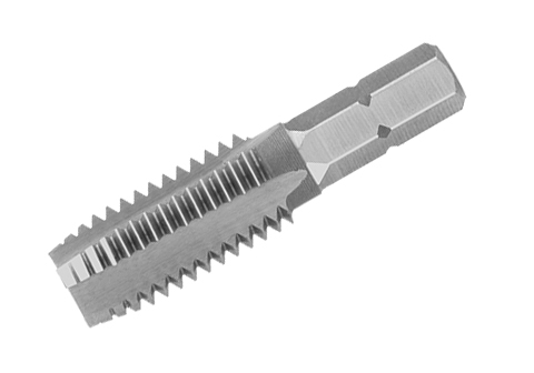
However, there is also a type of threads which is not being cut, but rather being rolled.
Rolled threaded products are often made with a reduced body diameter, approximately equal to the pitch diameter. When it is necessary to show this, the feature may be drawn as shown:

Diagram: Blank diameter; Major diameter of thread; Pitch diameter.
Here the thread is depicted bigger than the diameter of the part (both, in conventional and in alternative representations).